Phone Hack of French Minister Jean-Noël Barrot: A Cybersecurity Wake-Up Call
The phone hack of French Minister Jean-Noël Barrot during the G7 summit in November 2024 in Italy highlights critical vulnerabilities in high-level government communications. This sophisticated attack underscores the escalating cyber threats targeting global leaders. In this article, we examine the circumstances surrounding this breach, its profound implications for national security, and innovative solutions, such as DataShielder NFC HSM Defense, to effectively prevent such attacks in the future.
The G7 Summit and Its Strategic Importance
On November 24, 2024, Jean-Noël Barrot, the French Minister for Europe and Foreign Affairs, attended a bilateral meeting in Rome with his Italian counterpart, Antonio Tajani. This meeting laid the groundwork for discussions at the G7 Summit, held on November 25–26, 2024, in Fiuggi, near Rome.
The summit brought together foreign ministers from G7 nations to address critical global issues, including:
The war in Ukraine, with a focus on international coordination and humanitarian efforts.
Rising tensions in the Middle East, particularly the impact of regional conflicts on global stability.
Cybersecurity and disinformation, emerging as key topics amidst escalating cyber threats targeting governments and public institutions.
This context underscores the sensitivity of the discussions and the importance of secure communication channels, especially for high-level officials like Minister Barrot.
Explore More Digital Security Insights
🔽 Discover related articles on cybersecurity threats, advanced solutions, and strategies to protect sensitive communications and critical systems.
Quick Navigation
- The G7 Summit and Its Strategic Importance
- How the French Minister Phone Hack Exposed Cybersecurity Flaws
- ANSSI Investigations: Balancing Confidentiality and Speed
- Phishing: When the Hunter Becomes the Prey
- Expanding Risks Beyond Messaging Apps
- Challenges in Risk Management at the Highest Levels
- How DataShielder Could Have Prevented This Breach
- Recent Hacks Targeting French and European Officials
- Cyber Threats Across Europe: Why Encryption Is Vital
- Strengthening French Cybersecurity
- Unmatched Security and Encryption with DataShielder
- Closing the Loop: A Unified Cybersecurity Strategy
- From Personal Devices to National Threats: The Ripple Effects
- Key Takeaways for Cybersecurity
How the French Minister Phone Hack Exposed Cybersecurity Flaws
On November 25, 2024, cybercriminals targeted Jean-Noël Barrot, the French Foreign Minister, during the G7 summit. They launched the attack when Barrot unknowingly clicked on a malicious link sent through Signal, immediately granting them access to sensitive data. This breach underscores the urgent need for advanced encryption for national security to protect high-level communications from sophisticated cyber threats.
Shortly after, Bahrain’s Foreign Minister, Abdullatif Bin Rashid Al Zayani, noticed suspicious messages originating from Barrot’s device. This unusual activity quickly raised alarms and prompted further investigation. The incident demonstrates the importance of government cybersecurity solutions capable of mitigating threats from phishing, spyware, and other evolving attack vectors. (Mediapart)
Initial Investigations by ANSSI: Why Speed Matters
The Agence nationale de la sécurité des systèmes d’information (ANSSI), recognized for its ANSSI accreditation at the highest security levels (“Secret Défense”), quickly ruled out well-known spyware like Pegasus or Predator. However, the investigation faced delays due to Minister Barrot’s diplomatic commitments.
For detailed insights into similar spyware threats:
Phishing: When the Hunter Becomes the Prey
Ironically, Jean-Noël Barrot, who spearheaded a 2023 law against phishing, fell victim to this very tactic. This incident underscores how even cybersecurity-savvy individuals can be deceived by increasingly sophisticated attacks. This case underscores the critical need for robust tools in phishing attack mitigation. As attackers evolve their methods, even trusted platforms like Signal are exploited to orchestrate highly targeted phishing attacks.
Lessons from the Incident
- Phishing Evolution: Attackers exploit human vulnerabilities with precise, targeted messages.
- No One Is Immune: Even those fighting cyber threats can fall prey to them, highlighting the importance of robust defenses.
This case emphasizes the need for constant vigilance and tools like DataShielder NFC HSM Defense to mitigate such risks.
A Case Study: The French Minister’s Messaging Practices
In a public statement on November 29, 2023, Jean-Noël Barrot, French Minister for Europe and Foreign Affairs, revealed on X (formerly Twitter) that he and his team have been using Olvid, an ANSSI-certified messaging application, since July 2022. The minister described Olvid as “the most secure instant messaging platform in the world,” emphasizing its encryption and privacy features.
“It is French, certified by @ANSSI_FR, encrypted, and does not collect any personal data. We have been using it with my team since July 2022. In December, the entire government will use @olvid_io, the most secure instant messaging tool in the world.”
— Jean-Noël Barrot on X
Despite Olvid’s certification, the G7 summit breach in November 2024 occurred via Signal, another widely used secure messaging app. This raises critical questions:
- Inconsistent Platform Use: Even with access to highly secure tools like Olvid, alternative platforms such as Signal were still employed, exposing potential gaps in security practices.
- Persistent Human Vulnerabilities: Cybercriminals exploited human behavior, with Minister Barrot unknowingly clicking on a malicious link—a reminder that even the most secure tools cannot compensate for user error.
How DataShielder Could Have Prevented This Breach
Unlike standalone secure messaging apps, DataShielder NFC HSM Defense provides proactive multichannel encryption, ensuring the security of all communication types, including SMS, MMS, RCS, and messaging platforms such as Signal and Olvid. Sensitive communication protection is a cornerstone of DataShielder NFC HSM Defense. This advanced tool offers significant counter-espionage benefits, including:
- Cross-Platform Security: All communications are encrypted with AES-256 CBC, a quantum-resistant algorithm, via an NFC-secured device with patented segmented keys and multifactor authentication. This ensures robust protection across any platform used.
- Device Compromise Mitigation: Even if an Android phone, computer, or cloud-based messaging service is compromised, encrypted messages and files remain completely inaccessible. This ensures that sensitive data is protected against unauthorized access, whether from legitimate or illegitimate actors.
- Automated Call and Contact Protection: Sensitive contact data is securely stored outside the device, preventing theft. Additionally, all traces of calls, SMS, MMS, and related logs are automatically erased from the phone after use, significantly reducing the risk of exposure. Powered by the innovative EviCall NFC HSM technology, this feature ensures unparalleled communication security. Watch the video below to see how EviCall protects calls and contact information:
For additional details, visit: EviCall NFC HSM – Phone & Contact Security
- Seamless Integration: Officials can maintain their current habits on any platform while benefiting from elevated security levels, eliminating reliance on platform-specific encryption protocols.
By leveraging DataShielder NFC HSM Defense, governments can bridge the gap between user convenience and robust security, ensuring that high-level communications are safeguarded against sophisticated attacks exploiting human vulnerabilities or platform inconsistencies.
The Challenges of Risk Management at the Highest Levels
Jean-Noël Barrot’s refusal to hand over his hacked phone to ANSSI investigators raises questions about balancing confidentiality and collaboration. The incident also highlights the broader G7 cybersecurity challenges, particularly the complexity of securing sensitive communications in a rapidly evolving threat landscape. Solutions like DataShielder NFC HSM Defense are pivotal in addressing these challenges while safeguarding data sovereignty.
Implications of Non-Cooperation
- Delayed Investigations: Slows response times to attacks.
- Public Trust: Questions arise about leadership transparency and risk management.
- Solutions: DataShielder NFC HSM Defense allows secure investigation without exposing sensitive data, ensuring both collaboration and confidentiality.
Such tools could resolve the dilemma of balancing privacy with the need for swift cybersecurity responses.
Institutional Trust and National Cybersecurity: The Role of the ANSSI
The involvement of ANSSI in managing incidents like the French Minister Phone Hack raises important questions about institutional trust and operational protocols. While ANSSI is the national authority for cybersecurity, accredited to handle even the most sensitive information, this case exposes potential hesitations among top officials to fully cooperate during crises. As an organization with ANSSI accreditation, the agency is responsible for certifying tools used in national defense. Yet, the hesitations highlight a need for greater institutional trust, especially in the context of the G7 cybersecurity challenges.
Why ANSSI’s Role Is Pivotal
As the leading agency for protecting France’s critical infrastructures and sensitive information systems, ANSSI holds the highest levels of security clearance, including “Secret Défense” and “Très Secret Défense.” It has the technical expertise and legal mandate to investigate cyber incidents affecting government officials, such as:
- Cyberattack response to safeguard critical systems and recover compromised data.
- Certification of security solutions used in national defense and high-level communications.
- Collaboration with international agencies to combat global cyber threats.
These capabilities make ANSSI indispensable in incidents like the G7 phone hack, where sensitive diplomatic communications are at risk.
Perceived Hesitations: A Question of Trust?
Despite ANSSI’s credentials, Minister Jean-Noël Barrot’s delayed cooperation in submitting his device for forensic analysis raises questions:
- Could there be a lack of trust in sharing sensitive data with ANSSI, even though it operates under strict confidentiality protocols?
- Is this delay a reflection of the need for even greater assurances regarding data sovereignty and privacy during investigations?
While ANSSI adheres to strict security standards, the hesitations underscore a potential gap between technical accreditation and political confidence. This gap is where tools like DataShielder could make a critical difference.
DataShielder: Bridging the Gap Between Security and Trust
Solutions like DataShielder NFC HSM Defense address both the technical and trust-related challenges highlighted in this case:
- Preserving Data Sovereignty: DataShielder ensures that encrypted communications remain inaccessible to any unauthorized party, even during forensic investigations.
- Facilitating Confidential Collaboration: With tools like encrypted logs and automated data management, sensitive data can be analyzed without compromising its confidentiality.
- Building Institutional Confidence: The use of DataShielder demonstrates a proactive approach to protecting national interests, providing additional assurance to government leaders that their data remains fully secure and private.
Key Takeaway
The French Minister Phone Hack not only underscores the need for robust cybersecurity tools but also highlights the importance of strengthening trust between national institutions and decision-makers. By integrating advanced encryption solutions like DataShielder, governments can ensure both the security and confidence needed to navigate the complex challenges of modern cyber threats.
How DataShielder Could Have Changed the Game
The French Minister Phone Hack highlights the urgent need for advanced cybersecurity tools. If Jean-Noël Barrot had used DataShielder NFC HSM Defense, this innovative solution could have provided unparalleled safeguards while enabling seamless collaboration with cybersecurity investigators like ANSSI. Sensitive communications and data could have remained secure, even under intense scrutiny, mitigating risks associated with platform vulnerabilities or human errors.
Moreover, DataShielder aligns with international cybersecurity standards such as NIS2, positioning governments at the forefront of digital security while offering a proactive defense against escalating global cyber threats.
These challenges underline why solutions like DataShielder NFC HSM Defense are critical to addressing the rising threats effectively and safeguarding sensitive communications at all levels.
Unmatched Security and Encryption with DataShielder
DataShielder NFC HSM Defense ensures end-to-end encryption for all communication channels, including SMS, MMS, RCS, and messaging platforms like Signal, Olvid, and LinkedIn, using AES-256 CBC encryption, a quantum-resistant algorithm.
- Automated Protection: Sensitive contacts are stored securely outside devices, and all traces of calls, messages, and logs are automatically erased after use, ensuring no exploitable data remains.
- Device Compromise Mitigation: Even if devices or platforms are breached, encrypted data remains inaccessible, preserving confidentiality.
Seamless Integration and Compatibility
DataShielder’s Zero Trust and Zero Knowledge architecture eliminates reliance on third-party platforms while ensuring user convenience:
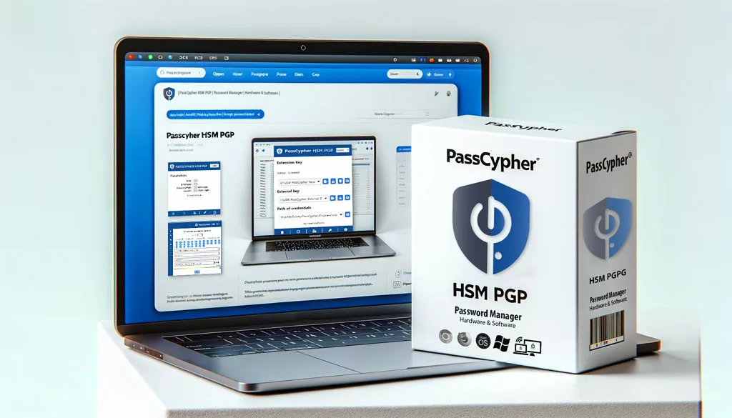
- Cross-Platform Functionality: Works with the DataShielder HSM PGP, EviCypher Webmail, and Freemindtronic Extension to encrypt and decrypt communications across all devices, including mini-computers like Raspberry Pi.
- User-Friendly Interface: Compatible with existing habits and workflows without sacrificing security.
Future-Proof Cybersecurity
DataShielder ensures communications are protected against emerging threats with:
- Resilience Against Quantum Attacks: Leveraging AES-256 CBC encryption.
- Sensitive communication protection: Maintaining full control of critical information while mitigating risks of compromise.
Phishing: A Persistent Threat to National Security
Phishing remains one of the most dangerous cyberattack vectors, with over 90% of cyberattacks originating from phishing emails, as reported by StationX. This alarming statistic underscores the critical need for robust security solutions like DataShielder to counter this pervasive threat.
Attackers now employ advanced tactics, such as highly convincing links and exploiting trusted platforms like Signal, to bypass basic defenses. This highlights the urgency for government cybersecurity solutions that integrate spyware protection tools and advanced encryption technologies, ensuring sensitive communications remain secure against evolving threats.
Expanding Risks Beyond Messaging Apps
Although Minister Barrot indicated that the attack originated from a link received via Signal, this incident is part of a broader trend of cyberattacks targeting communication platforms. These attacks are not limited to cybercriminals but often involve **state-sponsored cyberespionage groups** seeking to exploit trusted channels to gain access to sensitive government communications.
On December 4, 2024, the FBI and CISA (Cybersecurity and Infrastructure Security Agency) issued a joint advisory warning about the rise of SMS-based phishing attacks (smishing). These attacks use malicious links to lure victims into compromising their devices, exposing sensitive data. The advisory highlighted that these techniques are increasingly used by advanced persistent threats (APTs), often linked to nation-states.
The advisory emphasized that all communication platforms—SMS, messaging apps like Signal, and even emails—are vulnerable without robust security practices. Key recommendations include:
- Using strong encryption tools to safeguard communication.
- Carefully verifying links before clicking to avoid malicious redirects.
- Adopting advanced security devices, such as the DataShielder NFC HSM Defense, which protects sensitive communications even during espionage attempts. By encrypting data and implementing proactive defense mechanisms, this tool ensures that even if a platform is compromised, critical information remains secure.
This broader threat landscape underscores the increasing sophistication of cyberespionage actors and cybercriminals alike, who exploit trusted communication channels to target high-level government officials and agencies. In light of evolving cyber threats, these measures are indispensable for protecting national security and ensuring secure communication channels.
With advanced features like Zero Trust architecture and quantum-resistant encryption, tools like DataShielder provide unparalleled sensitive communication protection against both cybercriminal and cyberespionage threats.
Recent Hacks Targeting French and European Officials
Confirmed Espionage or Acknowledged Incidents
Over the years, reports and investigations have highlighted multiple high-ranking French officials as alleged targets of spyware like Pegasus and Predator. While some cases have been acknowledged, others remain under investigation or unverified. These incidents underscore vulnerabilities in governmental communication systems and the critical need for advanced cybersecurity measures.
Examples of High-Profile Targets
- Emmanuel Macron (President of France, 2021) – Confirmed as a target of Pegasus. Source
- Édouard Philippe (Former Prime Minister, 2021) – His phone was targeted by Pegasus. Source
- Jean-Yves Le Drian (Minister of Foreign Affairs, 2021) – Confirmed as a target of Pegasus. Source
- Christophe Castaner (Former Minister of the Interior, 2021) – Confirmed targeted by Pegasus. Source
- Gérald Darmanin (Minister of the Interior, 2021) – His phone was also targeted by Pegasus. Source
- Bruno Le Maire (Minister of Economy, Finance, and Recovery, 2021) – His phone was targeted by Pegasus. Source
- François Molins (General Prosecutor at the Court of Cassation, 2021) – His phone was targeted by Pegasus. Source
- Richard Ferrand (President of the National Assembly, 2021) – His phone was targeted by Pegasus. Source
- Éric Dupond-Moretti (Minister of Justice, 2021) – His phone was infected by Pegasus. Source
- François Bayrou (High Commissioner for Planning, 2021) – His phone was infected by Pegasus. Source
- Marielle de Sarnez (Former Minister of European Affairs, 2021) – Confirmed as a target of Pegasus. Source
Potential Targets (Presence on Pegasus List)
Some officials were identified as potential targets based on their presence in leaked surveillance lists, though there is no conclusive evidence of device compromise.
Examples of Potential Targets
- Jean-Noël Barrot (Minister for Europe and Foreign Affairs, 2024) Source
- Florence Parly (Former Minister of the Armed Forces, 2023) Source
- Jacqueline Gourault (Minister of Territorial Cohesion, 2020) source
- Julien Denormandie (Minister of Agriculture, 2020) source
- Emmanuelle Wargon (Minister of Housing, 2020) source
- Sébastien Lecornu (Minister of Overseas Territories, 2020) source
- Jean-Michel Blanquer (Minister of Education, 2019) source
- François de Rugy (Minister of Ecological Transition, 2019) source
Given these challenges, it becomes imperative to explore innovative solutions to address espionage risks effectively.
Challenges in Understanding the Full Extent of Espionage
Why Is the Full Extent of Espionage Unclear?
Understanding the full scope of spyware-related incidents involving government officials is fraught with challenges due to the complex nature of such cases.
Key Factors Contributing to Ambiguity
- Secrecy of Investigations: Details are often classified to protect evidence and avoid tipping off attackers.
- Political Sensitivity: Acknowledging vulnerabilities in official communication channels may erode public trust.
- Unconfirmed Compromises: Being listed as a potential target does not guarantee successful exploitation.
Strengthening French Cybersecurity with NFC Smartphones and DataShielder NFC HSM Defense
Sophisticated cyberattacks, such as the hacking of Jean-Noël Barrot’s phone, have exposed critical vulnerabilities in government communication systems. These threats highlight the urgent need to prioritize digital sovereignty and protect sensitive government communications. Combining French-designed NFC smartphones with the DataShielder NFC HSM Defense offers an effective and cost-controlled cybersecurity solution.
French Smartphone Brands Equipped with NFC Technology
Several French smartphone brands stand out for their NFC-equipped models, which integrate seamlessly with the DataShielder NFC HSM Defense. These brands, including Wiko, Archos, Kapsys, and Crosscall, cater to diverse users ranging from professionals to public agencies. Their NFC capabilities make them ideal for secure communication.
Brands Already Serving French Government Entities
Certain brands, including Crosscall and Kapsys, already supply French government entities, making them strong candidates for further adoption of advanced encryption solutions.
- Crosscall: Widely trusted by law enforcement and field professionals for its durable designs and reliability in harsh conditions.
- Kapsys: Kapsys delivers secure communication tools tailored for users requiring accessibility features and users with specific accessibility needs.
This established trust demonstrates the potential for these brands to further integrate cutting-edge tools like the DataShielder NFC HSM Defense into their offerings.
Unlocking Strategic Potential Through Collaboration
French smartphone brands can accelerate their contribution to national cybersecurity efforts by partnering with AMG Pro, the exclusive distributor of DataShielder NFC HSM Defense in France. Such collaboration enables the creation of comprehensive security packages, bundling NFC-enabled smartphones with state-of-the-art encryption technology.
A Strategic Synergy for Digital Sovereignty
Through collaboration with AMG Pro, French smartphone brands could:
By partnering with AMG Pro, French brands can:
- Enhance their reputation as leaders in sovereign technology through the integration of advanced cybersecurity tools.
- Offer comprehensive turnkey solutions, seamlessly combining smartphones with robust encryption to address the specific requirements of government entities.
- Contribute to advancing French digital sovereignty by promoting locally developed solutions designed to secure critical operations.
A Clear Path Toward Secure and Sovereign Communications
This strategy aligns with both economic priorities and national security goals, providing a robust response to the growing threat of cyberattacks. By leveraging French innovation and integrating advanced tools like the DataShielder NFC HSM Defense, French smartphone brands can pave the way for a secure, sovereign future in government communications.
Preventive Strategies for Modern Cyber Threats
The Importance of Preventive Measures
Governments must prioritize robust encryption tools like DataShielder NFC HSM Defense to counter espionage and cyber threats effectively.
Advantages of DataShielder
- Strong Encryption: Protecting communications with AES-256 CBC encryption, resistant to interception and exploitation.
- Proactive Surveillance Mitigation: Safeguarding sensitive communications, even if devices are targeted.
- User-Centric Security: Minimizing risks by automating data protection and erasure to counter human error.
Governments and organizations must prioritize these measures to mitigate risks and navigate the complexities of modern espionage.
Global Repercussions of Spyware Attacks
Global Impacts of Pegasus Spyware on World Leaders
Beyond France, global leaders have faced similar surveillance threats, highlighting the need for advanced encryption technologies to protect sensitive information.
Key Insight
These revelations emphasize the urgent need for robust encryption tools like DataShielder NFC HSM Defense to secure communications and mitigate risks. As cyber threats evolve, governments must adopt advanced measures to protect sensitive information.
Cyber Threats Across Europe: Why Encryption Is Vital
The issue of spyware targeting government officials is not limited to France.
European Parliament Members Targeted
In February 2024, traces of spyware were discovered on phones belonging to members of the European Parliament’s Subcommittee on Security and Defence. These findings emphasize the global scale of cyber surveillance and the need for robust security measures across governments. (Salt Typhoon Cyber Threats)
Key Takeaway
Cybersecurity is no longer optional—it is a strategic necessity for national sovereignty.
Why Encryption Tools Like DataShielder Are Crucial for Sensitive Communications
The French Minister Phone Hack demonstrates how advanced encryption for national security can mitigate risks associated with breaches. Tools like DataShielder NFC HSM Defense offer a proactive defense by ensuring end-to-end encryption for sensitive communications, making them an indispensable part of government cybersecurity solutions.This tool ensures comprehensive security for sensitive communications across platforms, safeguarding national interests.
Key Benefits of DataShielder
- Comprehensive Protection: Encrypts SMS, emails, chats, and files.
- Technological Independence: Operates without servers or central databases, reducing vulnerabilities.
- French Innovation: Built with 100% French-made origine components from French STMicroelectronics, leveraging patents by Freemindtronic founder Jacques Gascuel.
- Local Manufacturing: Designed and produced in France and Andorra, ensuring sovereignty and compliance.
- Ease of Use: Compatible with both mobile and desktop devices.
Cybersecurity: A Collective Responsibility
The hack targeting Jean-Noël Barrot shows that cybersecurity is not just an individual responsibility—it’s a collaborative effort.
Steps to Strengthen Cybersecurity
- Awareness Campaigns: Regular training for government officials to recognize cyber threats.
- Collaboration Across Agencies: Seamless cooperation for quick responses to threats.
- Adopting Encryption Tools: Technologies like DataShielder protect critical communications while ensuring compliance.
Governments must prioritize education, collaboration, and technology to safeguard national security.
Why Choose DataShielder?
- Comprehensive Protection: Encrypt SMS, emails, chats, and files.
- Technological Independence: Operates without servers or central databases, significantly reducing vulnerabilities.
- French and Andorran Innovation: Built with French-origin components and patents.
From Personal Devices to National Threats: The Ripple Effects of Cyberattacks
Breaches like the French Minister Phone Hack illustrate how compromised devices can have far-reaching implications for national security. Employing advanced encryption for national security through tools like DataShielder ensures that government cybersecurity solutions remain robust and future-proof.
Consequences of Breached Devices
- Diplomatic Risks: Compromised communications, such as those during the G7 summit, can strain alliances or expose strategic vulnerabilities, potentially leading to geopolitical tensions.
- Classified Data Leaks: Exposing sensitive plans or confidential discussions could provide adversaries with critical intelligence, undermining national interests.
How DataShielder NFC HSM Defense Helps
- Encrypted Protection: Ensures sensitive data remains secure even during investigations, preventing unauthorized access to classified information.
- Automatic Data Management: Removes sensitive logs, safeguarding user privacy while streamlining investigative processes.
Such tools bridge the gap between personal device security and national cybersecurity needs. Adopting tools like DataShielder is not just a technological upgrade—it’s a strategic necessity to safeguard national interests in a rapidly evolving digital landscape.
Strengthening Cybersecurity with Encryption Tools
Adopting tools like DataShielder NFC HSM and HSM PGP is a proactive step toward protecting sensitive communications. These devices provide security for governments, organizations, and individuals, ensuring sovereignty over critical data.
Secure Your Communications with DataShielder
To address the growing risks of cyber threats, DataShielder NFC HSM and HSM PGP provide robust encryption solutions designed to protect sensitive communications for both sovereign entities and professional applications.
Exclusivity in France
For users in France, DataShielder products are distributed exclusively through AMG Pro, offering tailored solutions to meet local regulatory and operational needs.
Availability in Other Countries
For international users, these solutions are available via FullSecure in Andorra. Explore the range of products below:
Available from FullSecure in Andorra. Explore the range of products below:
- DataShielder NFC HSM Master: A master encryption tool offering advanced security features for organizations and individuals.
- DataShielder NFC HSM Lite: A lightweight encryption solution perfect for everyday secure communication needs.
- DataShielder NFC HSM Auth: Ensures secure authentication and encryption for sensitive operations.
- DataShielder NFC HSM Starter Kit: An ideal entry point for comprehensive encryption and security.
- DataShielder NFC HSM M-Auth: Provides mobile-friendly encryption for on-the-go secure communication.
- DataShielder PGP HSM Data Encryption: A robust solution for secure file and email encryption.
Key Takeaways for Cybersecurity
The phone hack of French Foreign Minister Jean-Noël Barrot and similar breaches targeting other officials underline the critical need for strong cybersecurity protocols. Robust encryption tools like DataShielder NFC HSM and HSM PGP not only protect against known threats like Pegasus but also future-proof sensitive data from emerging cyber risks.
Now that we’ve highlighted the unique strengths of DataShielder, let’s discuss how governments can integrate this solution effectively to mitigate cyber threats and enhance operational security.
Implementing DataShielder in Government Operations
The French Minister Phone Hack demonstrates that advanced encryption solutions like DataShielder NFC HSM Defense are no longer optional—they are essential. Governments must act decisively to address escalating cyber threats and protect sensitive communications.
Why DataShielder Is the Answer:
- Fortify Communications
Cyberattacks on high-ranking officials, as seen in the G7 breach, expose the vulnerability of current systems. DataShielder offers unmatched encryption, shielding classified communications from prying eyes and ensuring uninterrupted confidentiality. - Enable Secure Investigations
By facilitating seamlThis tool facilitates seamless collaborationess collaboration with cybersecurity agencies like ANSSI while preserving the confidentiality of encrypted content, DataShielder strikes a perfect balance between privacy and judicial cooperation. This allows investigators to focus on analyzing attack methods without risking sensitive data. - Set a Gold Standard
Adopting DataShielder demonstrates a commitment to proactive cybersecurity measures. It establishes a precedent for managing sensitive data with operational transparency and national sovereignty, setting an example for global cybersecurity practices.
Protecting the Future
Integrating DataShielder NFC HSM Defense into government operations is not just a technological upgrade—it’s a necessary step toward a secure digital future. By equipping officials with cutting-edge tools, governments can:
- Safeguard classified data from cybercriminals and state-sponsored actors, ensuring the highest levels of security.
- Streamline investigative processes without compromising privacy, making crisis responses faster and more effective.
- Build public trust by showcasing robust and transparent management of cyber threats and national security.
Closing the Loop: A Unified Cybersecurity Strategy
As highlighted in the Key Takeaways for Cybersecurity, the need for robust encryption tools has never been more urgent. DataShielder NFC HSM Defense aligns perfectly with the priorities of governments seeking to protect national sovereignty and sensitive operations. With a future-proof solution like DataShielder, governments can confidently face emerging cyber risks, safeguard communications, and maintain trust in an increasingly digital world.
Adopting advanced encryption tools like DataShielder NFC HSM Defense is no longer optional—it is a strategic necessity. By acting decisively, governments can safeguard sensitive communications, protect national sovereignty, and set global standards in cybersecurity.


